So on 24th-Dec I was in my living room taking pictures of the mini Xmas tree and the fairy lights (photography is a hobby) when an idea popped into my head. I thought, “what if I can hack these fairy lights somehow so that instead of consuming batteries they run on mains power supply (steady 5v)? And if they can be made to blink that would be cool too. Can I use the Arduino board that I have and hook up some wires to do this?” Being a programmer by profession, I set out to convert this hypothesis into reality with trial-and-error. And let me make a disclaimer at this point that I didn’t Google for this and that this is my own original idea and work. If I had Googled it I wouldn’t be blogging about it, ofcourse, after I was done I did throw the query to Google just to see how many of such attempts have been already made and I wasn’t surprised to find a couple, though not a lot. So while this idea isn’t new, it did come to my mind motivated by my own need and was brought to fruition by my own work. Might I also add this is not an Arduino tutorial and I am assuming you know what Arduino is and are clear on the basics so if you don’t know what I am on about here, I would recommend reading tutorials on Arduino website first and then returning back if you are still interested.
In general a common fairy lights circuit looks like this:
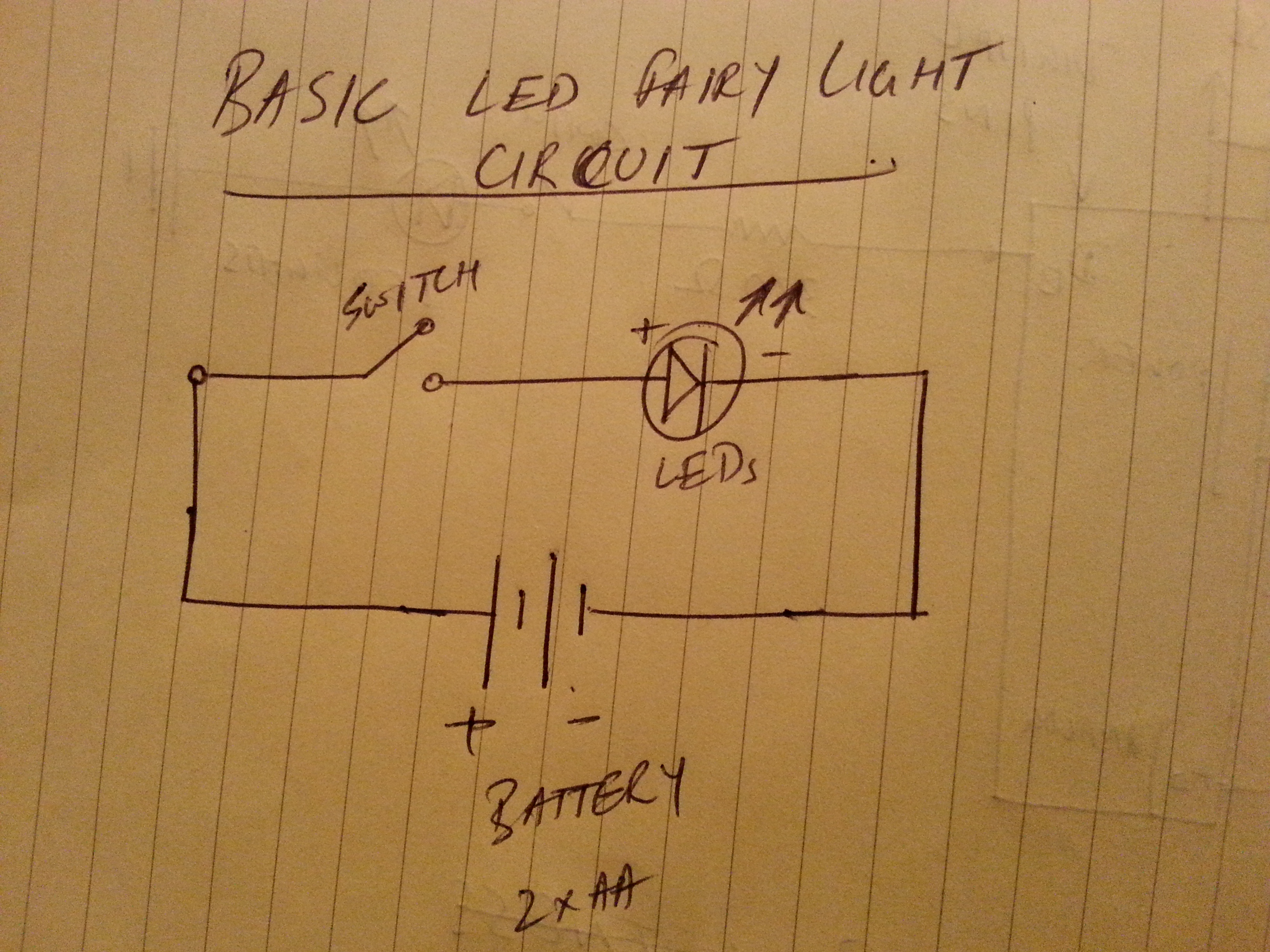
A pretty standard circuit, it connects the LED lights in parallel (all + together and all – together), because connecting them in series i.e. + of one into the – of another would put them in reverse bias and the LEDs won’t work. They only work in forward bias mode, + to + and – to -, much like a diode. A switch completes or breaks the circuit that powers the LEDs via one more AA cells. So instead of using those batteries, if I could connect the + of the switch to one of the digital pins on the Arduino board and the – of the switch to the ground pin, write an Arduino program that pulses the digital pin every 500 milliseconds and run it via the USB cable connected to my smartphone charger, I will have created blinking fairy lights instead of the monotonous always on lights as they come out of the box.
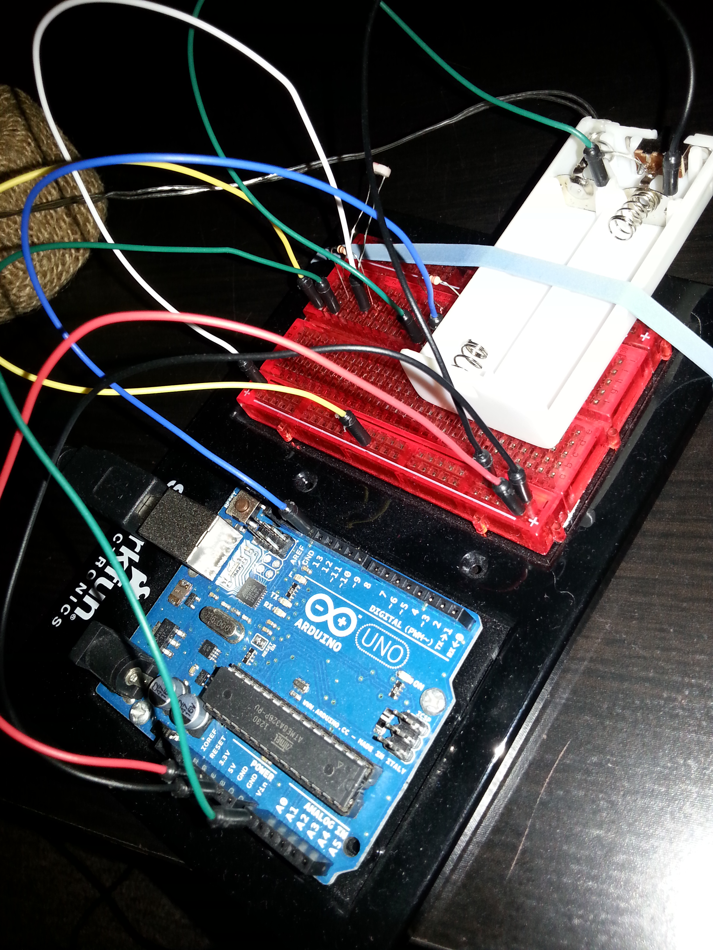
So the first version of the hack looked like this (I used Arduino Uno R3 board for this):

The corresponding Arduino code was even simpler:
int lightOutputPin = 13;

void setup()
{
  pinMode(lightOutputPin, OUTPUT);
}

void loop()
{
  long randomUpperLimit = random(10,501);
  //pattern 1: Heartbeat
  for(int i=0;i<randomUpperLimit;i++)
  {
    digitalWrite(lightOutputPin, HIGH);   // turn the LED on (HIGH is the voltage level)
    delay(100);               // wait for a second
    digitalWrite(lightOutputPin, LOW);    // turn the LED off by making the voltage LOW
    delay(100);               // wait for a second
    digitalWrite(lightOutputPin, HIGH);   // turn the LED on (HIGH is the voltage level)
    delay(100);               // wait for a second
    digitalWrite(lightOutputPin, LOW);    // turn the LED off by making the voltage LOW
    delay(1000);               // wait for a second
  }

  //pattern 2: Faster Heartbeat
  randomUpperLimit = random(10,501);
  for(int i=0;i<randomUpperLimit;i++)
  {
    digitalWrite(lightOutputPin, HIGH);
    delay(20);
    digitalWrite(lightOutputPin, LOW);
    delay(20);
    digitalWrite(lightOutputPin, HIGH);
    delay(20);
    digitalWrite(lightOutputPin, LOW);
    delay(20);
  }

  //pattern 3: normal blink
  randomUpperLimit = random(10,501);
  for(int i=0;i<randomUpperLimit;i++)
  {
    digitalWrite(lightOutputPin, HIGH);
    delay(randomUpperLimit ^ 101);
    digitalWrite(lightOutputPin, LOW);
    delay(randomUpperLimit ^ 201);
  }
}
As you can see the code does nothing more than keep running these 3 patterns forever. There is no other reason to use a “^” (XOR) operator than to just cause the delay to be random. Also, the number of times each loop runs is random too.
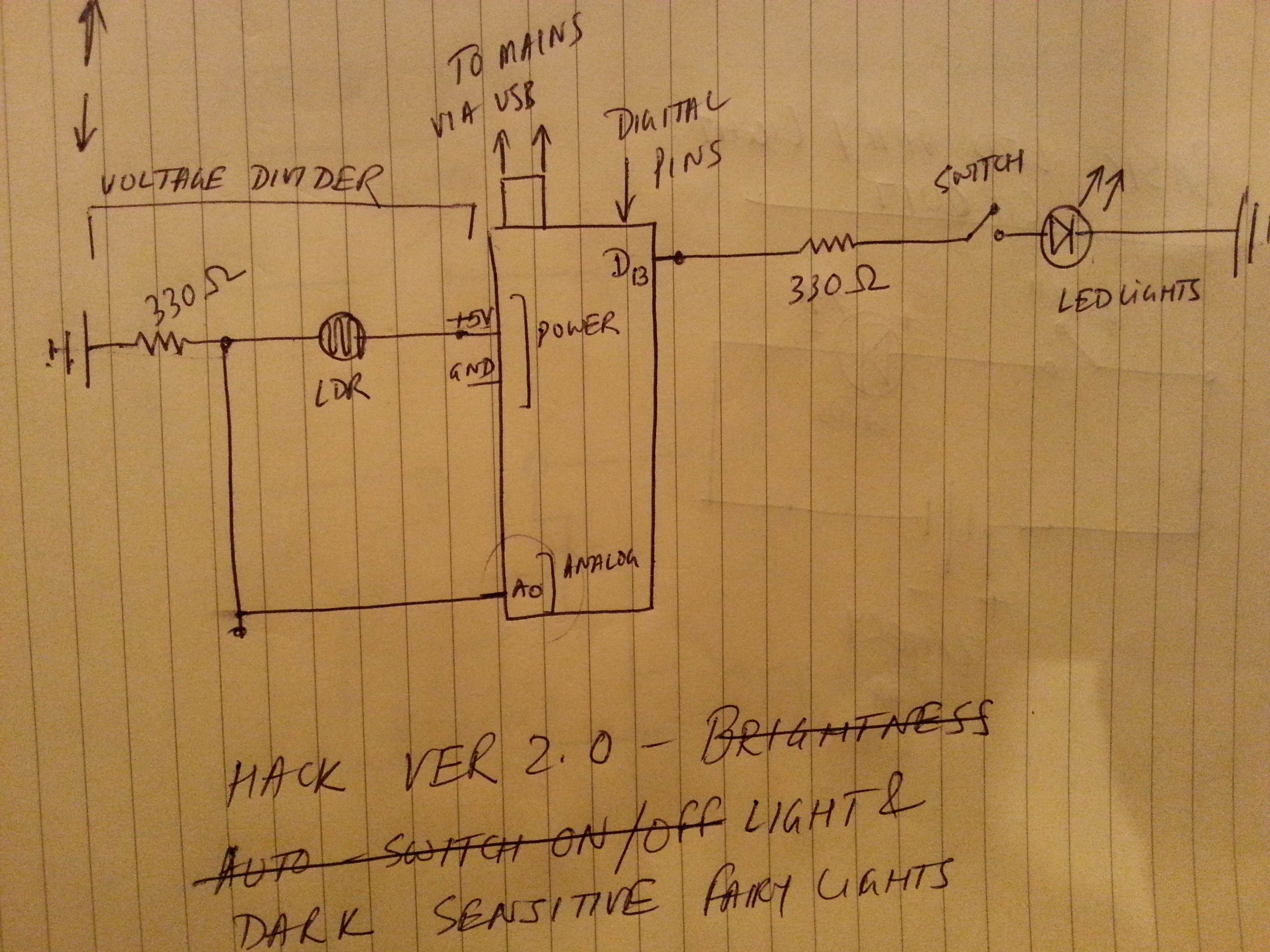
For version 2, I decided to add a Light Dependent Resistor (LDR) to automatically switch the LEDs off when its bright enough around and switch back on when it gets dark enough. For this, I read the values from LDR via the Analog pin 0 (A0) from the Arduino and kept trying until I found the one that will work just right for my settings. The circuit uses a voltage divider configuration on the LDR side and powers the LDR circuit by the +5v supply on Arduino board. When light levels are high, LDR’s resistance drops to almost zero allowing all the current to flow through it and when the light levels are low, the resistance is so high that almost no current flows through it. In either case, I was interested in finding out how the value changes across the LDR so I can see which values are for dark and which values are for light. Each analog pin can read 0 to 5V which maps to 1024 integer values ranging from 0 to 1023, which means every unit represents a change of 0.0049V or 4.9mV.
The LED side of things remained the same and the circuit schematic looked like this:
The corresponding Arduino code, which was also heavily refactored from the first version, was:
int lightOutputPin = 13;
int LDR = 0;

void setup()
{
  pinMode(lightOutputPin, OUTPUT);
//  Serial.begin(9600);
}

void HeartBeat()
{
  long randomUpperLimit = random(10,501);
  //pattern 1: Heartbeat
  for(int i=0;i<randomUpperLimit;i++)
  {
    if (!IsAmbientLightBright())
    {
      digitalWrite(lightOutputPin, HIGH);   // turn the LED on (HIGH is the voltage level)
      delay(100);               // wait for a second
      digitalWrite(lightOutputPin, LOW);    // turn the LED off by making the voltage LOW
      delay(100);               // wait for a second
      digitalWrite(lightOutputPin, HIGH);   // turn the LED on (HIGH is the voltage level)
      delay(100);               // wait for a second
      digitalWrite(lightOutputPin, LOW);    // turn the LED off by making the voltage LOW
      delay(1000);               // wait for a second
    }
    else
    {
      Reset();
      break;
    }
  }
}

void FasterHeartBeat()
{
  //pattern 2: Faster Heartbeat
  long randomUpperLimit = random(10,501);
  for(int i=0;i<randomUpperLimit;i++)
  {
    if (!IsAmbientLightBright())
    {
      digitalWrite(lightOutputPin, HIGH);
      delay(20);
      digitalWrite(lightOutputPin, LOW);
      delay(20);
      digitalWrite(lightOutputPin, HIGH);
      delay(20);
      digitalWrite(lightOutputPin, LOW);
      delay(20);
    }
    else
    {
      Reset();
      break;
    }
  }
}

void Blink()
{
  //pattern 3: normal blink
  long randomUpperLimit = random(10,501);
  for(int i=0;i= 100)
  {
    result = true;
  }

  //Serial.println(sensorReading);

  return result;
}

boolean IsAmbientLightBright()
{
  boolean result = false;
  int sensorReading = analogRead(LDR);
  /*
  *Each int value corresponds to 0.0049V. In a simple voltage
  * divider configuration, dark values range from 0 to 90-ish
  *bright values range from 100 to 500+. Theory: These values would depend on the value of the
  *resistor connected to the LDR in the voltdiv circuit. The higher the value, the higher the
  * voltage drop across the LDR and higher the sensor reading in both dark and bright situations
  */
  //double voltage = (double)(sensorReading * 0.0049);

  //when its bright, LED should switch off
  if (sensorReading >= 100)
  {
    result = true;
  }

  //Serial.println(sensorReading);

  return result;
}

void Reset()
{
  digitalWrite(lightOutputPin, LOW);
}

void loop()
{
  Blink();
  HeartBeat();
  FasterHeartBeat();
  delay(500);
}
The gist of the code is that for every blink pattern at each iteration check if the ambient light is bright enough, if it is then set the digital pin to LOW i.e. switch it off and break off from the loop otherwise keep blinking away until sunrise. Do keep in mind though, even in bright light conditions when the circuit seemingly is off, its still connected to the main power supply which is ON and this would cause the main loop() method to keep running and all the blink methods, its just that they would stay dormant if its too bright.
So this was a pretty neat and successful hack that took all of 30 minutes from conception to deployment and at the end of it all, my boring always on fairy lights had developed a heartbeat of their own (quite literally! ;)) and certainly looked good on the little Xmas tree of mine. Below are couple of more pictures of the circuit and the tree it lights up!